The precision of length measurements may be increased by using a device that uses a sliding vernier scale. Two such instruments that are based on a vernier scale which you will use in the laboratory to measure lengths of objects are the vernier callipers and the micrometer screw gauge. These instruments have a main scale (in millimetres) and a sliding or rotating vernier scale. In figure 1 below, the vernier scale (below) is divided into 10 equal divisions and thus the least count of the instrument is 0.1 mm. Both the main scale and the vernier scale readings are taken into account while making a measurement. The main scale reading is the first reading on the main scale immediately to the left of the zero of the vernier scale (3 mm), while the vernier scale reading is the mark on the vernier scale which exactly coincides with a mark on the main scale (0.7 mm). The reading is therefore 3.7 mm.

Figure 1 : The reading here is 3.7 mm.

Figure 1 : The reading here is 15.8 mm.
This Java applet will help you to understand how to read a vernier scale.
The vernier calipers
The vernier calipers found in the laboratory incorporates a main scale and a sliding vernier scale which allows readings to the nearest 0.02 mm. This instrument may be used to measure outer dimensions of objects (using the main jaws), inside dimensions (using the smaller jaws at the top), and depths (using the stem).

Figure 3: The vernier calipers
To measure outer dimensions of an object, the object is placed between the jaws, which are then moved together until they secure the object. The screw clamp may then be tightened to ensure that the reading does not change while the scale is being read.Watch this short movie to see how to do this.
Here is a nice vernier calipers applet.
The first significant figures are read immediately to the left of the zero of the vernier scale and the remaining digits are taken as the vernier scale division that lines up with any main scale division.
Some examples:
Note that the important region of the vernier scale is enlarged in the upper right hand corner of each figure.

Figure 4: The reading is 37.46 mm.
In figure 4 above, the first significant figures are taken as the main scale reading to the left of the vernier zero, i.e. 37 mm. The remaining two digits are taken from the vernier scale reading that lines up with any main scale reading, i.e. 46 on the vernier scale. Thus the reading is 37.46 mm.

Figure 5: The reading is 34.60 mm.
In figure 5 above, the first significant figures are taken as the main scale reading to the left of the vernier zero, i.e. 34 mm. The remaining two digits are taken from the vernier scale reading that lines up with any main scale reading, i.e. 60 on the vernier scale. Note that the zero must be included because the scale can differentiate between fiftieths of a millimetre. Therefore the reading is 34.60 mm.

Figure 6: The reading is 40.00 mm.
In figure 6 the zero and the ten on the vernier scale both line up with main scale readings, therefore the reading is 40.00 cm.
Try the following for yourself.

Figure 7: Click here for the answer.

Figure 8: Click here for the answer.

Figure 9: Click here for the answer.
The micrometer screw gauge
The micrometer screw gauge is used to measure even smaller dimensions than the vernier callipers. The micrometer screw gauge also uses an auxiliary scale (measuring hundredths of a millimetre) which is marked on a rotary thimble. Basically it is a screw with an accurately constant pitch (the amount by which the thimble moves forward or backward for one complete revolution). The micrometers in our laboratory have a pitch of 0.50 mm (two full turns are required to close the jaws by 1.00 mm). The rotating thimble is subdivided into 50 equal divisions. The thimble passes through a frame that carries a millimetre scale graduated to 0.5 mm. The jaws can be adjusted by rotating the thimble using the small ratchet knob. This includes a friction clutch which prevents too much tension being applied. The thimble must be rotated through two revolutions to open the jaws by 1 mm.
Here is a useful applet to learn how to use the micrometer screwgauge.

Figure 10: The micrometer screw gauge
In order to measure an object, the object is placed between the jaws and the thimble is rotated using the ratchet until the object is secured. Note that the ratchet knob must be used to secure the object firmly between the jaws, otherwise the instrument could be damaged or give an inconsistent reading. The manufacturer recommends 3 clicks of the ratchet before taking the reading. The lock may be used to ensure that the thimble does not rotate while you take the reading. Watch this short movie to see how to do this.
The first significant figure is taken from the last graduation showing on the sleeve directly to the left of the revolving thimble. Note that an additional half scale division (0.5 mm) must be included if the mark below the main scale is visible between the thimble and the main scale division on the sleeve. The remaining two significant figures (hundredths of a millimetre) are taken directly from the thimble opposite the main scale.

Figure 11: The reading is 7.38 mm.
In figure 11 the last graduation visible to the left of the thimble is 7 mm and the thimble lines up with the main scale at 38 hundredths of a millimetre (0.38 mm); therefore the reading is 7.38 mm.
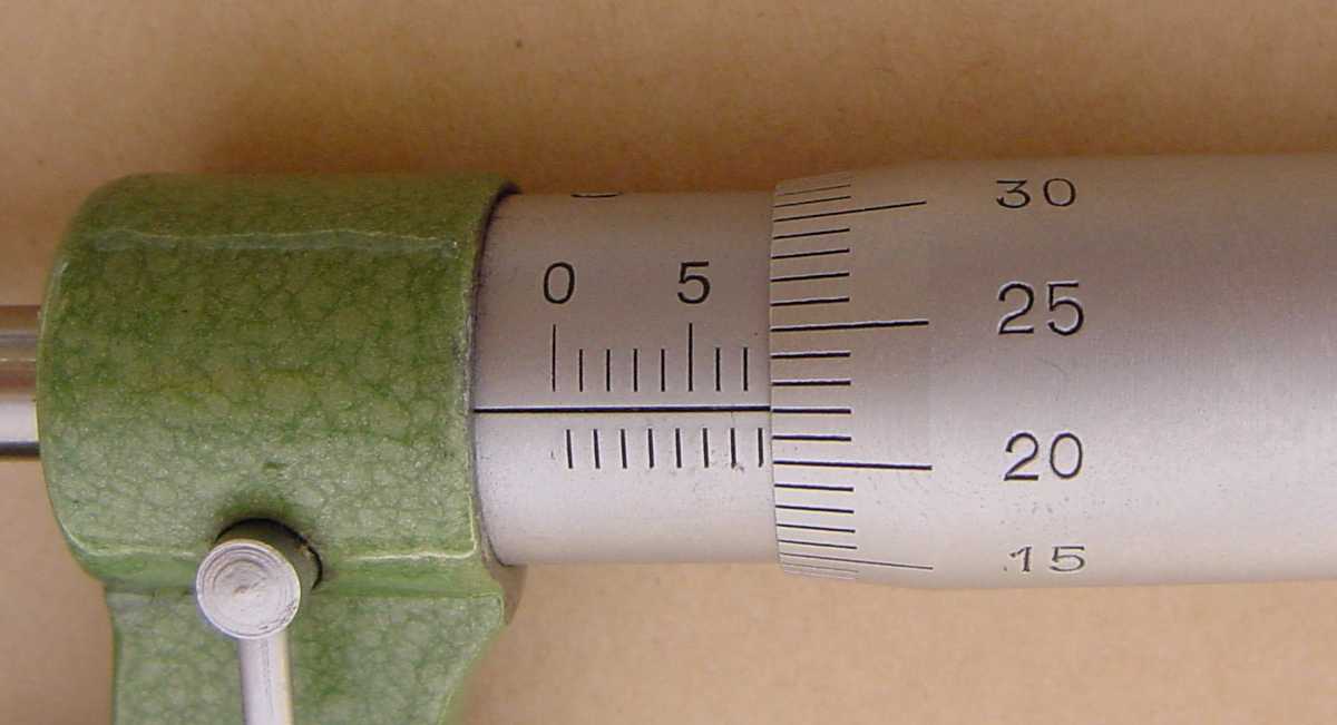
Figure 12: The reading is 7.72 mm.
In figure 12 the last graduation visible to the left of the thimble is 7.5 mm; therefore the reading is 7.5 mm plus the thimble reading of 0.22 mm, giving 7.72 mm.
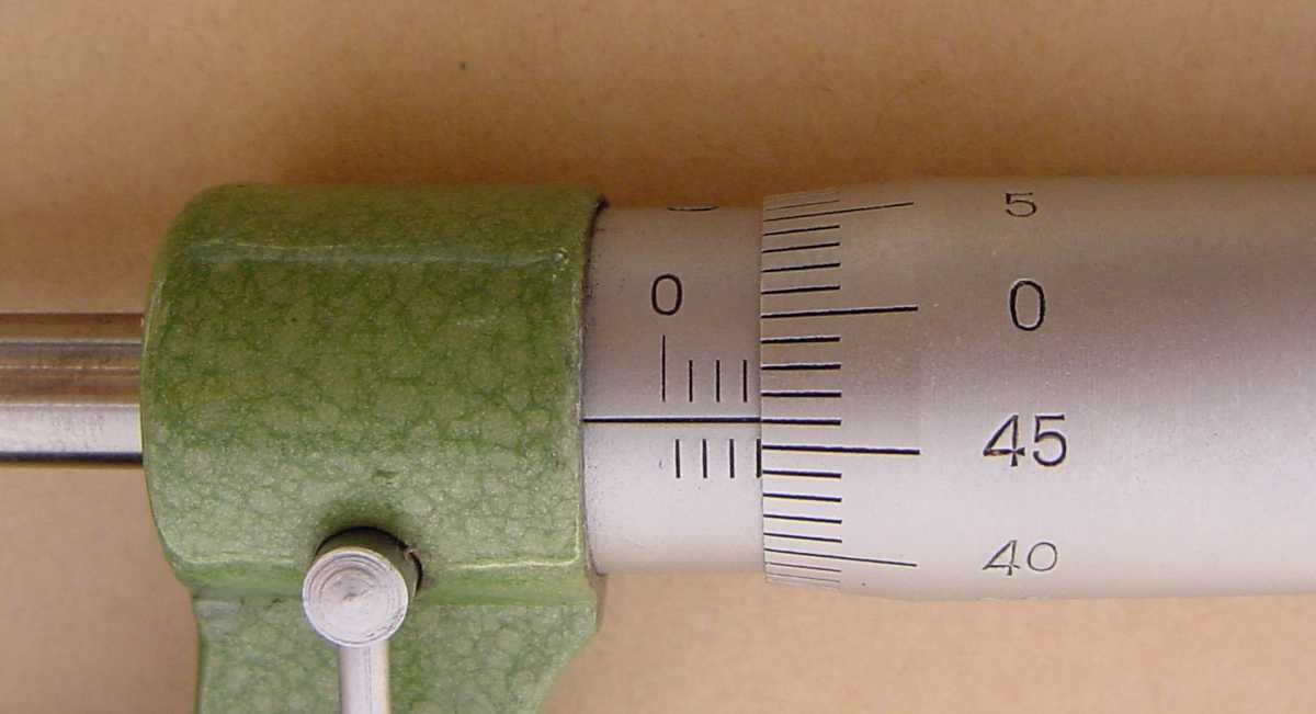
Figure 13: The reading is 3.46 mm.
In figure 13 the main scale reading is 3 mm while the reading on the drum is 0.46 mm; therefore, the reading is 3.46 mm.

Figure 14: The reading is 3.56 mm.
In figure 14 the 0.5 mm division is visible below the main scale; therefore the reading is 3.5 mm + 0.06 mm = 3.56 mm.
Try the following for yourself.
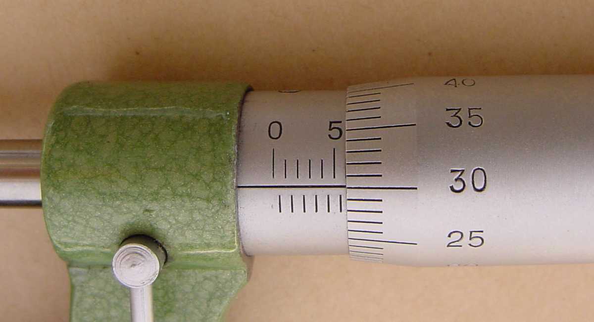
Figure 15: Click here for the answer.
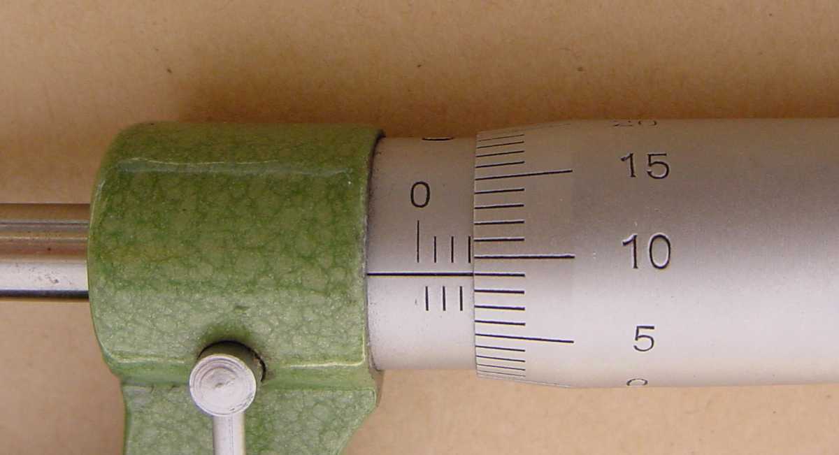
Figure 16: Click here for the answer.
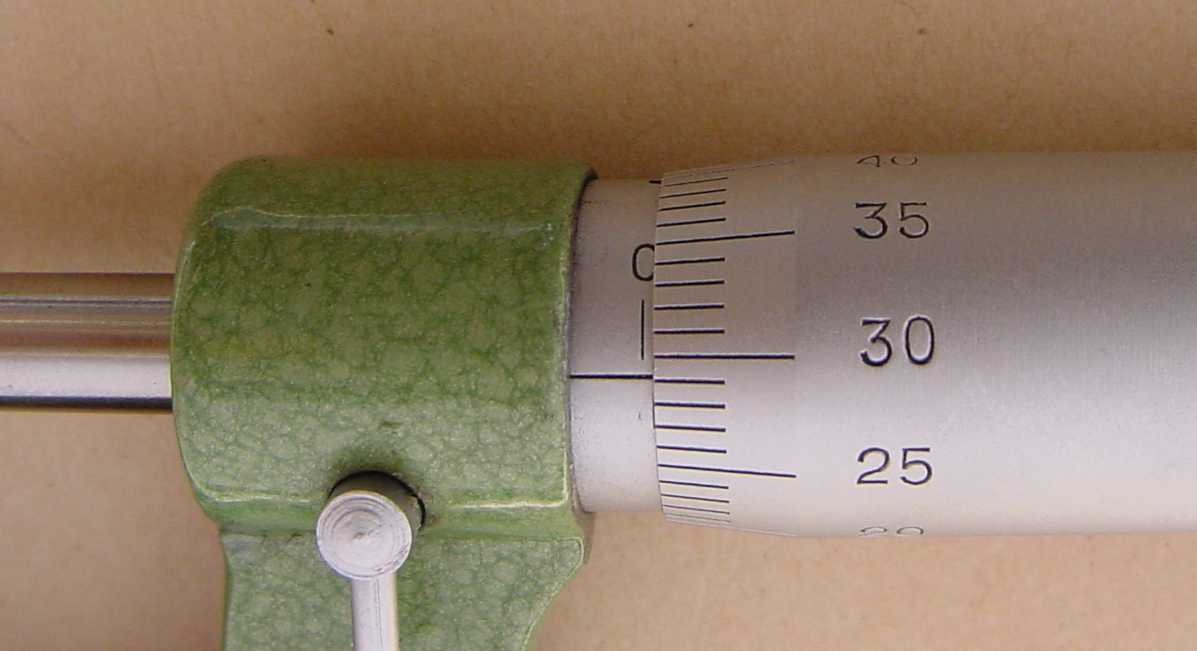
Figure 17: Click here for the answer.
Taking a zero reading
Whenever you use a vernier calipers or a micrometer screw gauge you must always take a �zero reading� i.e. a reading with the instrument closed. This is because when you close your calipers, you will see that very often (not always) it does not read zero. Only then open the jaws and place the object to be measured firmly between the jaws and take the �open� reading. Your actual measurement will then be the difference between your �open� reading and your zero reading.
Recording the result of your vernier measurement
Let us say you take a reading with an object between the jaws of a vernier calipers and you see the following:

Say that you decide that the best estimate of the reading l 1 is 37.46 mm.
What about the standard uncertainty u(l1) in this reading?
Using a triangular probability density function, you might decide that you are 100% sure that the reading is not 37.42 mm and 100% sure that the reading is not 37.50 mm.
Then
When you remove the object and read the vernier calipers with the jaws closed, you might decide that the best estimate of the "closed" reading l0 = 0.04 mm with standard uncertianty u(l 0) = 0.0204 mm
What should you then record as the best estmate of the length of the object you are measuring?
The best estimate of the length l = l 1 - l0 = 37.46 - 0.04 = 37.42 mm
with a standard uncertainty
Therefore l = 37.420 ± 0.026 mm (65% level of confidence).
Answers
Figure 7: 30.88mm
Figure 8: 8.10mm
Figure 9: 121.68mm
Figure 15: 5.80mm
Figure 16: 3.09mm
Figure 17: 0.29mm